
REGMIK product
Power Regulator RM1
- Price
- 3,330 UAH
- Availability
- In stock
The device monitors and controls power in an active load with one channel. Sensors with a unified current or voltage output signal can be used as setting devices.
Purpose:
The power regulator is designed for:
- controlling the power of an active load connected to the device by power triacs;
- use as a power setter for a heater with manual control, as well as for automatic temperature maintenance of an object jointly with thermostats (e.g., RD1, RP1, etc.).
General functions and operation modes:
The power regulator operates in automatic mode. When a control voltage of 0...10 V is supplied to the input, the device proportionally regulates the output power of the active load within 0...100%.
The device provides a smooth ramp-up to the set power. This is necessary to prevent sudden overloads of the power supply network. When the device is turned on or when there is a step change in the control input signal, the load power increases smoothly rather than abruptly. The time to reach the set power level is adjustable from 0.1 to 60 seconds and is set using the knob on the front panel of the device.
The "lock" input signal prohibits the generation of control pulses. When released, a smooth ramp-up to the set power level occurs. The "lock" signal source can be an NPN transistor with an open-collector output or contacts of a button, toggle switch, reed switch, or relay.
The operating mode is indicated on the front panel of the device and can be changed programmatically. Factory calibration of analog inputs is performed at the manufacturer with preservation of factory settings.
To regulate the power on the load, the device allows generating control signals for power triacs by two methods: phase-angle or by number of half-periods.
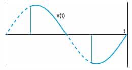
The phase-angle method is used for controlling low-inertia objects that respond to changes in voltage on the load, as well as for lighting control. In the phase-angle method, the device changes the triac firing angle depending on the control input signal level, thus changing the power level on the load.
The method of control by number of half-periods is applicable only to inertial loads. The number of half-periods applied to the load depends on the control input signal level: at minimum power level (0%) no voltage half-waves are applied, at maximum power level (100%) all half-waves are applied, and at 50% power level half of the voltage half-waves are applied.
Specifications
Parameters of Analog Inputs
| Characteristics | AN | AT |
|---|---|---|
| Operating mode | 2 | 3 |
| Factory settings | 0... 10 V | 4... 20 mA |
| Minimum calibrated value | 0 V | 0 mA |
| Maximum calibrated value | 10 V | 20 mA |
Main technical specifications of the power regulator
| Specification name | Value |
|---|---|
| Supply voltage (AC mains), V | 220 (± 15) |
| Mains frequency, Hz | 50 (± 10) |
| Power consumption, W | no more than 3 |
| Control mode of device | control signal 0...10 V |
| Method of power triac control | mode №1 - phase-angle mode №2 - pulse (by number of periods) |
| Width of device, mm | 67 |
| Weight, g (max) | 400 |
Dimming of LED Lamps by "Phase Cut" Method
Trailing Edge Dimming

Leading Edge Dimming
Reviews
Customer reviews
There are no reviews yet.
Only verified customers can add reviews.
Open customer cabinet